

Yes, they can all be used in the weaving land, there is instruction on how to calculate the slope. For the lateral move, the maximum slop is 5%, but 30% for center pivot. More about the slope calculate, please find the “pivot slope design” page!
You need just tell us your CFR quotation and the destination port, we will enquire our forwarder COSCO about the freight cost and plus it in the quotation sheet.
No, diesel generator is just an option for your choice. If not illustrated independently, we will quote with electric power acquirescently. But lateral move quotation has the diesel generator included.
Yes, both technology development and production capacity comply with American and European standards. Our products meet the ISO 9001:2008 for center pivot production, and all the steel parts are hot dip galvanized, which meet the USA galvanization standards of pivot manufactures ASTM A 123/123m-02.
Yes, we have, the followings are the details:
Guarantee of pivot/lateral move
- 1 year concerning electric equipment
- 8 years/8000 working hours for gearboxes and gear motors whichever expires earlier
- 20 years concerning the galvanized equipment against corrosion
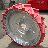
- 3 years for tires and rims
We guarantee our equipment and its service ability against all materials or construction defects.
It depends on the quantity and specification you order. We have some standard machines in stock, which can be shipped ahead, but if you have some special options and requirements, we need to produce for you independently and tell you the shipping time.
For the lateral move, it normally takes longer time especially for the ditch feed, because the main cart has pump + diesel engine + alternator and we also have to leave some time to suppliers.
It depends on the order, but you can find the exact amount at the first page’ bottom of the quotation sheet we sent to you.
Yes, we have set up a worldwide dealer net, they are all professional and can help you install and maintain quickly. But there will be extra charge for this service, if you need, please tell us about the details.
What is the inlet pressure of center pivot? What is your sprinklers’ distance?
All these and much more information you can find on the second page in section Technical data, Timer and etc of our quotation sheet.
For the machine, you can just order 1 set, but if just the parts, you have to order a big quantity. But there are exceptions, if you are our old customers or you have had our machine but just require spare parts, we can accept the relative small order.
We can accept 30% down payment by T/T and 70% by L/C or T/T before shipment.
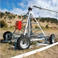
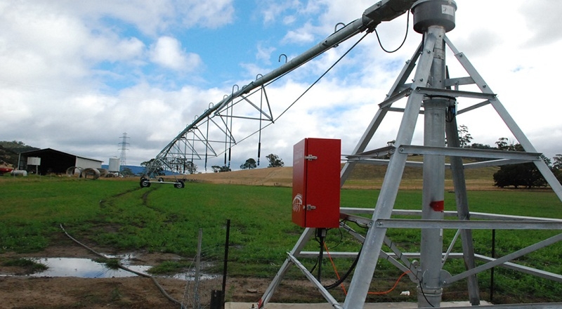
Our products can be classified into three kinds – Fixed center pivot, Towable center pivot and Lateral move system.
The difference between them is mainly the move mode. For the fixed one, one end of the machine is fixed and other spans move clock wise by motor drive tires. For the towable one, three or four wheels are assembled on the center part of the pivot, which makes the system moved by towing the pivot point with tractor. For the lateral move, all the machines work in linear movement by motor driven tires to irrigate rectangle area. Unlike center pivot systems, where the area irrigated depends only on the length of the machine, lateral system area is determined by two factors: system length and travel distance.
Towable center pivot can be maximum 500m for safe towing, but fixed one can be longer.
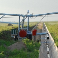
Compared with them, the length of lateral move depends on the water source – ditch feed or hose feed. A ditch feed machine gets water from the built ditch, concrete or earth. Hose feed machine gets water from hose with the underground pipeline with hydrants. For the hose feed, the maximum length is 450m.
For details, please return to the machine page, you can know much about our machines!
The maximum length of towable center pivot is 500m for safety tow. We can make longer for you but the warranty will be limited and not apply on towing.
For the fixed center pivot and lateral move, we can make up to 800m long.
If your field is square and you didn’t choose the lateral move, you may need end gun to spray the area uncovered. The corner control system can make the end gun spraying under your setting angle, or it will spray all the time, which causes unnecessary waste.
There are some conditions that the pivot can not finish a full rotation according to your field such as the terrain, obstacles, houses and so on. Now the auto stop and reverse system is needed. A touch device is installed in the tower of the pivot, when hit by the rod connected, the pivot can reverse automatically.
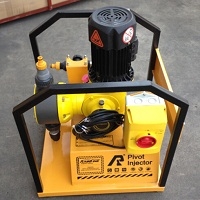
Yes, you can use our chemical injector on more than one machine such as center pivot and lateral move systems. The chemical injector is small and easily transferred by just one person. It can also promise the safety of livings, you can find the details on the introduction.
No, it is very simply and you can learn it within 1 hour. You nearly need to do nothing with the help of control panel, it can realize auto work. We are also working on the remote control and will come out soon.
No, we have not yet but just in planning in the near future. This system is very expensive and very rare customers ask for this kind of machine.
The price depends on the machine you choose and some related information. For the machine, we have center pivot – fixed or towable and lateral move, we need also to know the water source you prefer – ditch or hose feed.
Then you should tell us your crops and the water application rate for the center pivot. These all decide the sprinklers we choose for you and different type with different price. Please give us your field area, if lateral move you choose, also its length and width in meters.
There are some conditions that the pivot can not finish a full rotation according to your field such as the terrain, obstacles, houses and so on. Now the auto stop and reverse system is needed. A touch device is installed in the tower of the pivot, when hit by the rod connected, the pivot can reverse automatically.
know about pivot
The center pivot is the system of choice for agricultural irrigation because of its low labor and maintenance requirements, convenience, flexibility, performance and easy operation. When properly designed and operated, and equipped with high efficiency water applicators, a center pivot system conserves three precious resources—water, energy and time.
Manufacturers have recently improved center pivot drive mechanisms (motors, gears and shafts), control devices, optional mainline pipe sizes and outlet spacings, span lengths, and structural strength. The first pivots produced in the 1950s were propelled by water motors. They operated at high pressures of 80 to 100 psi and were equipped with impact sprinklers and end guns that sprayed water toward the sky, resulting in significant evaporation losses and high energy use. Today, pivots are driven by electric or oil hydraulic motors located at each tower and guided by a central control panel. Pressures as low as 10 to 15 psi (at the pivot mainline) are usually adequate for properly designed LESA (low elevation spray application) and LEPA (low energy precision application) pivots that are 1/4 mile long operating on level to moderately sloping fields. Water application efficiency with such systems is 85 to 98 percent.
Pivot Design Choices
When purchasing a center pivot system one must select:
■ mainline size and outlet spacing;
■ length, including the number of towers;
■ drive mechanisms;
■ application rate of the pivot;
■ the type of water applicator.
These choices affect investment and operating costs, irrigation efficiency, and crop production. Wise decisions will result in responsible water management and conservation, flexibility for future changes, and low operating costs.
Switching from furrow to pivot irrigation can save water and money. For example, on the Texas High Plains, field measurements show that corn is irrigated an average of 16 to 17 hours per acre per year with furrow irrigation. With center pivot MESA irrigation (over canopy applicators), similar corn yields are produced with 12 to 13 hours per acre per year. LEPA and LESA applicators further reduce irrigation to an average of 10 to 11 hours per acre per year.
Wheel and Drive Options
The travel speed is determined by the wheel size in combination with the power drive mechanism, and is set at the central control panel. The speed of the pivot determines the amount of water applied as specified on the corresponding system design precipitation chart. (See the following discussions on the system design precipitation chart and system management as related to travel speed. Gear drives should be checked for proper oil levels and any water in the gear boxes removed at least once each year.)
Electric power drive has two gear reductions. One gear reduction is in the drive shafts connecting the electric motor to a gear box located at each of the two tower wheels. The second gear reduction is the gear box driving each wheel. The maximum center pivot travel speed depends on the:
■ electric motor speed or rotation in revolutions per minute (RPM);
■ speed reduction ratios in both the center drive shafts and gear boxes; and
■ wheel size.
Design Printout
The design computer printout provides required information about the center pivot and how it will perform on a particular tract of land. A portion of a typical design printout includes:
■ the pivot design flow rate (or system capacity) in GPM;
■ irrigated acreage under the pivot;
■ elevation changes in the field as measured from the pivot point;
■ operating pressure and mainline friction losses;
■ the pressure regulator rating in psi (if used);
■ the type of water applicator, spacing and position from the mainline;
■ nozzle size for each applicator;
■ water applicator nozzle pressure;
■ maximum travel speed;
■ the precipitation chart.
It is essential that correct information about available water supply (in GPM) and changes in field elevation are used in designing the pivot so that accurate irrigation amounts, operating pressure requirements, and the need for pressure regulators can be determined. Give this information to your dealer, and then inspect the resulting computer design printout before placing your order to ensure that the system is designed to accommodate your site conditions and will perform as expected. Always look at the design mainline operating pressure at the pad to determine if it is what you want. If not, inquire about ways to lower it.
System Capacity
System irrigation capacity is determined by the gallons per minute (GPM) and the number of acres irrigated. System capacity is expressed in terms of either the total flow rate in GPM or the application rate in GPM per acre. Knowing the capacity in GPM per acre helps in irrigation water management. These irrigation amounts apply for all irrigation systems with the same capacity in GPM per acre. The amounts do not include application losses, and are for systems operating 24 hours a day. To determine your system’s capacity, select the desired irrigation amounts in inches and multiply the corresponding GPM per acre by the number of acres you are irrigat- ing. For example, if you irrigate 120 acres with 4 GPM per acre, 480 GPM (120 acres x 4 GPM per acre) are required to apply 0.21 inches per day, 1.50 inches per week, and 6.40 inches in 30 days.
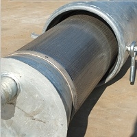
Mainline Pipe Sizing
Mainline pipe size influences the total operating cost. Smaller pipe sizes, while less expensive to purchase, may have higher water flow friction pressure loss, resulting in higher energy costs. Plan new center pivots to operate at minimum operating pressure to minimize pumping cost.
Some dealers may undersize the mainline in order to reduce their bids, especially when pushed to give the best price. Check the proposed design printout. If operating pressure appears high, ask the dealer to provide another design using proportional lengths, usually in spans, of larger pipe, or to telescope pipe to reduce operating pressure. Saving money on the initial purchase price often means paying more in energy costs over the life of the system.
Telescoping involves using larger mainline pipe at the beginning and then smaller sizes as the water flow rate (GPM) decreases away from the pivot point. Typical mainline sizes are 10, 8 1/2, 8, 6 5/8 and 6 inches. Mainline pipe size governs options in span length (the distance between adjoining towers).
Telescoping mainline pipe size is a method of planning a center pivot for minimum water flow friction loss and low operating pressure, and thus, lower pumping costs. Telescoping uses a combination of pipe sizes based on the amount of water (GPM) flowing through. Telescoping is usually accomplished in whole span lengths. Its importance increases with both higher flow rates (GPM) and longer center pivot lengths. Dealers use computer telescoping programs to select mainline pipe size for lowest purchase price and operating costs.
Pressure Regulators
Pressure regulators are “pressure killers.” They reduce pressure at the water delivery nozzle so that the appropriate amount of water is applied by each applicator. Selection of nozzle size is based on the rated delivery psi of the pressure regulators. Nozzles used with 10 psi regulators are smaller than those used with 6 psi regulators when the same amount of water is applied. Low rated (psi) pressure regulators, if used, allow center pivot design to be appropriate at minimum operating pressure.
Pressure regulators require energy to function properly. Water pressure losses within the regulator can be 3 psi or more. So, entrance (or inlet) water pressure should be 3 psi more than the regulator rating. Six-psi regulators should have 9 psi at the inlet; 10-psi regulators, 13 psi; 15-psi regulators, 18 psi; and 20-psi regulators, 23 psi. Regulators do not function properly when operating pressure is less than their rating plus 3 psi. Pressure regulator operating inlet pressure should be monitored with a gauge installed upstream adjacent to the regulator in the last drop at the outer end, and should be checked when the machine is upslope. Another gauge located in the first drop in span one will monitor operating pressure when the center pivot is located on downslope terrain.
Pressure regulator psi rating influences system design, appropriate operating pressure, the total energy requirements, and the costs of pivot irrigation.
As with other spray and sprinkler systems, pressure regulators are not necessarily needed for all sites.
Elevation changes in the field have the largest impact with lower design pressures. From the first to last drop on a pivot, the operating pressure at the nozzle should not vary more than 20 percent from the design operating pressure. Without regulators, operating pressure and pumping cost usually will not increase significantly if the elevation does not change more than 5 feet from the pad to the end of the pivot. Where elevation changes are greater than 5 feet, the choice is to increase operating pressure (and probably pumping costs) or to use pressure regulators. This decision is site specific and should be made by comparing the extra costs of pressure regulators to the increased pumping costs without them.
Where the water flow rate, and thus the operating pressure, vary significantly during the growing season, perhaps from seasonal variations in groundwater pumping levels, the design flow rate (or system capacity) and the use of pressure regulators should be evaluated carefully. If water pressure drops below that required to operate the regulators, then poor water application and uniformity will result. In contrast, if the design operating pressure is high, pumping costs will be unnecessarily high. When operating pressure decreases to less than required, the solution is to renozzle for the reduced gallons per minute. The amount of water flow in the mainline decreases or increases operating pressure for the nozzles installed.
Water Applicators
Pads
There are various types of spray applicators available, each with pad options. Low-pressure spray applicators can be used with flat, concave or convex pads that direct the water spray pattern horizontally, upwards and downwards at minimum angles. Spray applicator pads also vary in the number and depth of grooves they have, and, thus, in the size of water droplets they produce. Fine droplets may reduce erosion and runoff, but are less efficient because of their susceptibility to evaporation and wind drift. Some growers prefer to use coarse pads that produce large droplets, and control runoff and erosion with agronomic and management practices. There is little published data on the performance of various pad arrangements. In the absence of personal experience and local information, following the manufacturer’s recommendations is likely the best strategy in choosing pad configuration. Pads are very inexpensive. Some growers purchase several groove configurations and experiment to determine which works best in their operation.
Impact Sprinklers
High-pressure impact sprinklers mounted on the center pivot mainline were prevalent in the 1960s when energy prices were low and water conservation did not seem so important. Now, high-pressure impacts are recommended only for special situations, such as the land application of wastewater, where large nozzles and high evaporation can be beneficial.
Impact sprinklers are usually installed directly on the mainline and release water upward at 15 to 27.
Low-pressure Applicators
Very few center pivots in Texas are now equipped with impact sprinklers. There are improved applicators and design technology for more responsible irriga-tion water management. These new ap-plicators operate with low water pressure and work well with current center pivot designs. Low-pressure applicators require less energy and, when appropriately positioned, ensure that most of the water pumped gets to the crop.
The choice is which low-pressure applicator to use and how close to ground level the nozzles can be. Generally, the lower the operating pressure requirements the better. When applicators are spaced 60 to 80 inches apart, nozzle operating pressure can be as low as 6 psi, but more applicators are required than with wider spacings (15 to 30 feet). Water application is most efficient when applicators are positioned 16 to 18 inches above ground level, so that water is applied within the crop canopy. Spray, bubble or direct soil discharge modes can be used.
Field testing has shown that when there is no wind, low-pressure applicators positioned 5 to 7 feet above ground can apply water with up to 90 percent efficiency. However, as the wind speed increases, the amount of water lost to evaporation increases rapidly. In one study, wind speeds of 15 and 20 miles per hour created evaporative losses of 17 and 30+ percent, respectively. In another study on the southern High Plains of Texas, water loss from a linear-move system was as high as 94 percent when wind speed averaged 22 miles per hour with gusts of 34 miles per hour.
Evaporation loss is significantly influenced by wind speed, relative humidity and temperature.
The following sections describe three types of low-pressure application systems that can significantly reduce operating pressure and deliver most of the water pumped for crop production.
MESA
With Mid-Elevation Spray Application (MESA), water applicators are located approximately midway between the mainline and ground level. Water is applied above the crop canopy, even on tall crops such as corn and sugar cane. Rigid drops or flexible drop hoses are attached to the mainline gooseneck or furrow arm and extend down to the water applicator. Weights should be used in combination with flexible drop hose. Nozzle pressure varies depending on the type of water applicator and pad arrange ment selected. While some applicators require 20 to 30 psi operating pressure, improved designs require only 6 to 10 psi for conventional 8 1/2 to 10-foot mainline outlet and drop spacing. Operating pressures can be lowered to 6 psi or less when spray applicators are positioned 60 to 80 inches apart. With wider spacings, such as for wobbler and rotator applicators, manufacturers’ recommended nozzle operating pressure is greater.
Research has shown that in corn production, 10 to 12 percent of the water applied by abovecanopy irrigation is lost by wetting the foliage. More is lost to evaporation. Field comparisons indicate that there is 20 to 25 percent more water loss from MESA above- crop-canopy irrigation than from LESA and LEPA within-crop-canopy center pivot systems.
LESA
Low Elevation Spray Application (LESA) applicators are positioned 12 to 18 inches above ground level, or high enough to allow space for wheel tracking. Less crop foliage is wet, especially when planted in a circle, and less water is lost to evaporation. LESA applicators are usually spaced 60 to 80 inches apart, corresponding to two crop rows. The usual arrangement is illustrated in Figure 6. Each applicator is attached to a flexible drop hose, which is connected to a gooseneck or furrow arm on the mainline. Weights help stabilize the applicator in wind and allow it to work through plants in straight crop rows. Nozzle pressure as low as 6 psi is best with the correct choice of water applicator. Water application efficiency usually averages 85 to 90 percent, but may be less in more open, lower profile crops such as cotton. LESA center pivots can be converted easily to LEPA with an applicator adapter that includes a connection to attach a drag sock or hose.
The optimal spacing for LESA drops is no wider than 80 inches. With appropriate installation and management, LESA drops spaced on earlier, conventional 8 1/2- to 10-foot spacing can be suc- cessful. Corn should be planted in circle rows and water sprayed underneath the primary foliage. Some growers have been successful using LESA irrigation in straight corn rows at conventional outlet spacing when using a flat, coarse pad that sprays water horizontally. Grain sorghum and soy- beans also can be planted in straight rows. In wheat, when plant foliage causes significantly uneven water distribution, swing the applicator over the truss rod to raise it. (Note: When buying a new center pivot, choose a mainline outlet spacing of 60 to 80 inches, corresponding to two row widths.)
LEPA
Low Energy Precision Application (LEPA) irrigation discharges water between alternate crop rows planted in a circle. Water is applied with:
■ applicators located 12 to 18 inches above ground level, which apply water in a “bubble” pattern; or
■ drag socks or hoses that release water on the ground.
Socks help reduce furrow erosion; double-ended socks are designed to protect and maintain furrow dikes. Drag sock and hose adapters can be removed from the applicator and a spray or chemigation pad attached in its place when needed. Another product, the LEPA “quad” applicator, delivers a bubble water pattern that can be reset to optional spray for germination, chemigation and other in-field adjustments.
LEPA applicators typically are placed 60 to 80 inches apart, corresponding to twice the row spacing. Thus, one row middle is wet and one is dry. Dry middles allow more rainfall to be stored. Applicators are arranged to maintain a dry row for the pivot wheels when the crop is planted in a circle. Research and field tests show that crop production is the same whether water is applied in every furrow or in alternate furrows. Applicator nozzle operating pressure is typically 6 psi.
Field tests show that with LEPA, 95 to 98 percent of the irrigation water pumped gets to the crop. Water application is precise and concentrated, which requires a higher degree of planning and management, especially with clay soil. Center pivots equipped with LEPA applicators provide maximum water application efficiency at minimum operating pressure. LEPA can be used successfully in circles or in straight rows. It is especially beneficial for low profile crops such as cotton and peanuts, and even more beneficial where water is limited.
Chemigation
Chemigation is the application of an approved chemical (fertilizer, herbicide, insecticide, fungicide or nematicide) with irrigation water through the center pivot. Chemigation is an improved, advanced concept. Pesticide and other chemical labels must state whether the product is approved for application in this way. If so, application instructions are provided on the label. EPA regulations require the use of specific safety control equipment and devices designed to prevent accidental spills and contamination of water supplies. Using proper chemigation safety equipment and procedures also aids the grower by providing consistent, precise and continuous chemical injection, thus reducing the amounts (and costs) of chemicals applied. As in Texas, state regulatory agencies may have their own requirements in addition to those of the EPA. For more information contact your county Extension office or state Department of Agriculture.
Advantages of chemigation
■ Uniformity of application. With a properly designed irrigation system, both water and chemicals can be applied uniformly, resulting in excellent distribution of the water-chemical mixture.
■ Precise application. Chemicals can be applied where they are needed and in the correct concentrations.
■ Economics. Chemigation is usually less expensive than other application methods, and often requires a smaller amount of chemical.
■ Timeliness. Chemigation can be carried out when other methods of application might be prevented by wet soil, excessive wind, lack of equipment, and other factors.
■ Reduced soil compaction and crop damage.
Because conventional in-field spray equipment may not be needed, there could be less tractor wheel soil compaction and crop damage.
■ Operator safety. The operator is not in the field continuously during applications, so there is less human contact with chemical drift, and less exposure during frequent tank fillings and other tasks.
Disadvantages of Chemigation
■ Skill and knowledge required. Chemicals must always be applied correctly and safely. Chemigation requires skill in calibration, knowledge of the irrigation and chemigation equipment, and an understanding of the chemical and irrigation scheduling concepts.
■ Additional equipment. Proper injection and safety devices are essential and the grower must be in compliance with these legal requirements.
Fertigation
The application of fertilizers with irrigation water, or fertigation, is often referred to as “spoon-feeding” the crop. Fertigation is very common and has many benefits. Most fertigation uses soluble or liquid formulations of nitrogen, phosphorus, potassium, magnesium, calcium, sulfur and boron. Nitrogen is most commonly applied because crops need large amounts of it. Keep in mind that nitrogen is highly soluble and has the potential to leach; it needs to be carefully managed.
There are several nitrogen formulations that can be used for fertigation. Be sure a solid formulation is completely dissolved in water before it is metered into the irrigation system. (Up to three, 80-pound bags of nitrogen fertilizer can be dis- solved in a 55-gallon drum.) This may require agitating the mixture for several hours. Continue agitating throughout the injection process.
Advantages of Fertigation
■ Nutrients can be applied any time during the growing season based on crop need.
■ Mobile nutrients such as nitrogen can be carefully regulated in the soil profile by the amount of water applied so that they are available for rapid use by the crop.
■ Nutrients can be applied uniformly over the field if the irrigation system distributes water uniformly.
■ Some tillage operations may be eliminated, espe- cially if fertilization coincides with the application of herbicides or insecticides. However, do not inject two chemicals simultaneously without knowing that they are compatible with each other and with the irrigation water.
■ Groundwater contamination is less likely with fertigation because less fertilizer is applied at any given time. Application can correspond to maximum crop needs.
■ There is minimal crop damage during fertilizer application.
Disadvantages of Fertigation
■ Fertilizer distribution is only as uniform as the irrigation water distribution. Use pressure gauges to ensure that the center pivot is properly pressured.
■ Lower cost fertilizer materials such as anhydrous ammonia often cannot be used.
■ Fertilizer placement cannot be localized, as in banding.
■ Ammonia solutions are not recommended for fertigation because ammonia is volatile and too much will be lost. Also, ammonia solutions tend to precipitate lime and magnesium salts, which are common in irrigation water. Such precipitates can form on the inside of irrigation pipelines and clog nozzles. The quality of irrigation water should be evaluated before using fertilizers that may create precipitates. Besides ammonia, various polyphosphates (e.g., 10-34-0) and iron carriers can react with soluble calcium, magnesium and sulfate salts to form precipitates.
■ Many fertilizer solutions are corrosive. Chemigation injection pumps and fittings constructed of cast iron, aluminum, stainless steel and some forms of plastic are less subject to corrosion and failure. Brass, copper and bronze are easily corroded. Know the materials of all pump, mixing and injector components that are in direct contact with concentrated fertilizer solutions. Table 8 describes the corrosion potential of various metals when in direct contact with common commercial fertilizer solutions.
Center Pivot Checklist
Pivot Design
Actual lowest and highest field elevation irrigated in relation to the pivot point was used in the computer design printout.
Actual measured or reduced flow rate and pressure available by pump or water source was used in the computer design printout.
Friction loss in pivot mainline for quarter-mile-long systems is no greater than 10 psi.
Mainline size is telescoped to achieve selected operating pressure.
Mainline outlets are spaced a maximum of 60 to 80 inches or, alternately, two times the crop row spacing.
Gauges are included at the pad and last drop to monitor operating pressure.
For non-leveled fields, less than 20 percent variation in system design operating pressure is maintained when pivot is positioned at the highest and lowest points in the field (computer design printout provided for each case).
Pressure regulators were evaluated for fields with more than 5 feet of elevation change from pad to the highest and the lowest point in the field.
Tower wheels and motor sizes were selected based on desired travel speed, soil type and slope, following manufacturer’s recommendations.
Operation control provides expected performance.
The dealer provided a copy of the pivot design printout.
Applicators
No end gun.
Consideration was given to equipping the pivot with either LEPA or LESA applicators as follows:
LEPA (low energy precision application)
a) option 1
multi-functional LEPA head with an operating pressure requirement of 6 psi, positioned 1 to 1.5 feet above the ground, spaced at two times the crop row spacing flexible drop hose from gooseneck or furrow arm on mainline to applicator, equipped with a polyweight or other type of weight.
b) option 2
Spray applicator with an operating pressure requirement of no more than 10 psi, located 1 to 1.5 feet above the ground. For row crops, spray applicator is equipped with an exchangeable plate to allow for attachment of a drag hose or double-ended sock flexible drop hose from gooseneck or furrow arm on mainline to applicator, equipped with a polyweight or other type of weight spray pad groove design for maximum efficiency
LESA (low elevation spray application)
spray applicators with an operating pressure requirement of no more than 10 psi, located 1 to 2 feet above the ground, spaced 5 to 6 feet apart flexible drop hose from gooseneck or furrow arm on mainline to applicator, equipped with a poly-weight or other type of weight
Installation, Water and Power Supply
Pivot pad constructed to manufacturer’s specifications.
Subsurface water supply pipeline to pivot point is sized for water velocity of no more than 5 feet per second.
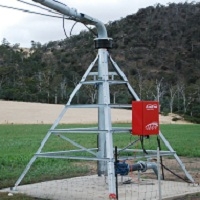
Power supply to pivot follows manufacturer’s specifications; may be a power unit, power unit and generator, or subsurface power lines.
Accessories
Propeller flow meter or other type of flow measurement device with an accuracy of ± 3 percent, and instantaneous flow rate and totalizer indicators, installed in water supply pipeline near pivot point in a straight section ten pipe diameters upstream and five pipe diameters downstream from the flow meter.
Two pressure gauges—one on the mainline near the pivot and one in the last drop, located just above the applicator or pressure regulator.
Computer control panel for fields with soil changes and/or multi-crop situations.
Remote control/monitoring system (optional).
Chemigation unit meets federal safety requirements and is tied into computer control panel or power shut-off system. Injector pump is sized according to the pivot flow rate and travel speed.
note: the information above is from Leon New-Professor and Extension Agricultural Engineer Irrigation & Guy Fipps -Professor and Extension Agricultural Engineer The Texas A&M System